


Artificial Intelligence Substation Control
Abstract
Controlling a substation by a unclear controller will anyhow speeds up the comeback time and diminish the possibility of risks usually related to human operations. The automation of electric substation is an area under constant progress.
While the research has been focused on, the Selection of the magnitude to be controlled, Definition and implementation of the soft techniques. However the elaboration of a programming tool to execute the control operations is possible to control the desired status while supervising some important magnitudes like the voltage, power factor, and harmonic distortion, as well as the present status.
Though the status of the circuit breakers can be control by using a knowledge base that relates some of the operation magnitudes, mixing status variables with time variables and fuzzy sets; still the number of necessary magnitudes to supervise and to control a substation can be very high as per recent requirements and research work. However, many magnitudes were not included to avoid the extensive number of required rules nevertheless, controlling a substation by a fuzzy controller has the advantage that it can speed up the response time and diminish the possibility of risks that are normally related with human operations.
Introduction
Electric substations are the facilities in charge of the voltage transformation to provide safe and effective energy to the consumers. hence the energy supply has to be carried out with sufficient quality and should guarantee the equipment security. The associated cost to ensure quality and security during the supply in substations will be high. While the automatic mechanisms are generally used in greater or lesser scale, although they mostly operate according to an individual control and protection logic related with the equipment itself and not with the topology of the whole substation in a given moment.
The automation of electric substation is an area under constant development. however, to control a substation is a very complex task due to the interconnected and related problems and, therefore, the decision variables that can influence the substation performance. Under such circumstances, the use of learning control systems can be very useful.
Let us see on the difficulties associated with the application of this technique include:
- Selection of the magnitude has to be controlled
- Implementation of the soft techniques should be appropriate
- Elaboration of a programming tool to execute the control operations on, acquisition and installation of the measurement and control equipment
- Interface with the proper equipment
- Applications of the controlling technique in existent substations
Even when all the magnitudes are controlled they cannot be included in the analysis more often than not due to the great number of capacity and status variables of the substation and, thus to some rules that would be required by the controller), it is possible to control the desired status while supervising some important magnitudes as the voltage, power factor, and harmonic distortion, as well as the present status.
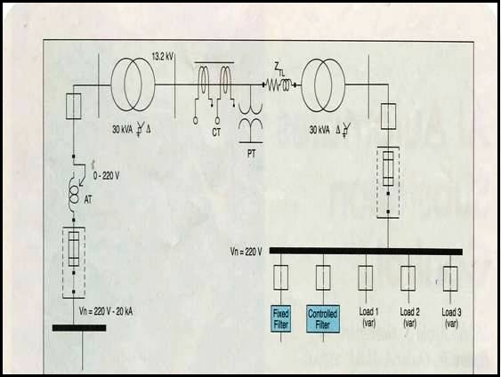
The system under study represents a test substation with two 30KVA three-phase transformers, two CBs, two switches, three current transformers, and two potential transformers. Therefore the auto transformer to regulate the input voltage as well as impedance to simulate the existence of a transmission line. The input voltage are the same (220V), this characteristic was selected in order to analyze the operation of the controller in a laboratory scale in a second stage of the progress of the present work.
Therefore, the first transformer increases the voltage to a value of 13.2KV, while the second lowers it again to 220V. Fixed filter, and an automatic filter for the control of the power factor and the regulation of the voltage, and three feeding lines with diverse type of loads of different nature including nonlinear loads are associated through CBs to the output bar.
Since the control elements in substations are the CBs and switches, the goal is to allow the control of the five selected CBs in the output bar according to some configurations and measurements of the observation variables. Initially, the computer-aided system will try to control the plant and will send alarm signals when it cannot find a solution, waiting for the human intervention. So it will learn how the human operator reacts to the inputs and will produce the corresponding behavior rules. In this way, the system will replace regularly the human operator.
Definition Of N The Input And Output Variables
There are a great number of variables that can be chosen to control a substation. However, a limited number of variables were selected for this study. The following input variables have been defined:
- Vout: Voltage at output bus, phase A (V).
- PF: power factor at output bus, phase A
- THDv(%):Total voltage harmonic distortion at output bus(%)
- Tv, t(s): Amount of time the voltage Vout is in range [114.3V;119.5V]- tolerance zone
- Tv,nt(s): Amount of time the voltage Vout is below 114.3V- alert zone
In selecting the variables, several aspects were kept in mind. For example, the voltage influences in the connection and disconnection of loads when its value leaves some ranges during certain time.
A reduce of the voltage 7.5% below the nominal value is allowed during a certain time for example, 10 min, while from 10% on, the maximum allowed time is much smaller for example, 20 s. In case these limits are exceeded, loads will be disconnected in an established preference order. The reconnection of loads will occur when the voltage arrives at values above the tolerance interval, i.e., and the normal interval.
On the other hand, the power factor and the total voltage harmonic distortion influence the connection and disconnection of capacitor and filters. These variables can be read by means of sensors and/or transducers, including signal conditional accessories and directed to the data acquisition card (DAC) by means of analog lines. In this example, the currents and voltages in each phases are not kept in mind due to the great number of rules that would be required by the controller.
The CBs were defined as status variables. The switches were not included in this study, because their status is only important for switching and not for control purposes.
Here are the following status variables defined:
- Df: Status of the CB connecting the fixed filter
- Dc: Status of the CB connecting the controlled filter
- D11,D12,D13: Status of the CBs connecting the load feeders 1,2, and3
Each combination of status variables defines a topology and is an input for the controller. Possible values for each status variable are 0(open) and 1 (closed). Thus, what is intended to control is the moment when the filters and the loads should be connected or disconnected by means of signals that are sent to the CBs. The controlled filter, once connected, will maintain its functionality as an automatic filter in dependence of the present harmonic distortion over the time. In case of a disconnection of some filter due to over currents, the controller can activate connection rules after some time that can be freely defined before the controller starts.
The actions to carry out as a response to disturbances in the measurements values out of normal ranges are dependent not only on the present topology of the substation, i.e., on the values of the present status variables. For example; the connection of the controlled filter can only occur when the fixed filter is connected. Similarly, the disconnection of the fixed filter can only occur after the controlled filter has been disconnected.
The status variables are input and also output variable. Each CB will maintain its standard protection function against over currents. Since signal to these devices are sent by means of additional relays to have the ability to be controlled in parallel. The status variables are read by sensors and/or transducer and connected to digital lines to a DAC. Digital lines to the CB relays also send the outputs. For the definition of sets, triangular and trapezoidal shape functions were used. The status variables were not fuzzified because their measurement are not provided with uncertainty. They can only accept two values:0 and 1. The time the voltage is in tolerable and not tolerable ranges is supervised through the event counters.